Antenna design made simple
Planning and cutting antenna wires often raises the same questions: how long should the dipole arms be?, what if I use insulated wire?, or how much do I need to trim if the resonance is off?
This calculator helps you estimate the correct lengths for common amateur-radio antennas (dipoles, verticals, EFHW, Inverted-V, trap and fan dipoles, W3DZZ, etc.), taking into account shortening factors, insulation, and even feedline effects. You can switch between metric and US units, use preset amateur bands, and save your own designs.
Enter your frequency and antenna type below to get started. For more detailed analysis, open the Advanced panel for bandwidth, feedline, and tuning suggestions.
Antenna Length & Feedline Calculator
Understanding Antenna Length: A Complete Guide for Radio Enthusiasts
Why antenna length matters
If you’ve ever built or tuned an antenna, you’ve probably asked yourself: How long should this wire be? At first, it seems simple—just take the well-known formula 300 divided by frequency in MHz, and you’ve got your answer. But in practice, things are rarely that straightforward. The wire’s insulation, its thickness, the type of antenna, the feedline you use, and even nearby trees or rooftops all play a role in how long the antenna really needs to be.
Getting the length right is more than just a matter of neatness. When an antenna resonates properly:
-
It’s far more efficient at turning transmitter power into radiated RF energy.
-
Your transceiver will thank you, because low SWR means less stress and no automatic power reductions.
-
You’ll often notice better signal reports and clearer reception.
-
And perhaps most importantly, you won’t waste hours trimming, soldering, and re-hanging wires trying to find the sweet spot.
That’s why an antenna length calculator isn’t just a gadget. It’s a timesaver, a teacher, and in many cases, the difference between frustration and success on the air.
The fundamentals of wavelength and resonance
Before we dive into the different types of antennas, let’s remind ourselves of a few basics.
Wavelength
Radio waves move at the speed of light, which is about 300,000 kilometers per second. If you divide that speed by the frequency, you get the wavelength. For example:
So at 14.2 MHz (the popular 20-meter amateur band), one full wavelength is about 21.1 meters. A half-wave antenna would be roughly half that—10.55 meters—before applying any corrections.
Resonance
When we say an antenna is resonant, we mean that its reactance is close to zero at a given frequency, leaving mostly resistance. A resonant antenna is easier to match, often shows a low SWR, and usually doesn’t need much in the way of matching networks or tuners.
Velocity factor and shortening
Here’s where things get tricky. Real wires don’t behave like perfect mathematical lines. Insulation around the wire and even the proximity of the ground slow the current down. We express this with something called the velocity factor (VF). For bare copper, VF is usually around 0.96–0.98, while for insulated wire it can be closer to 0.90–0.95.
That’s why the simple 300/f formula almost always gives you an antenna that’s too long. In practice, we multiply by a shortening factor to get closer to the real resonant length.
Dipole antennas: the starting point
The classic half-wave dipole is where most of us start. It’s straightforward: two equal arms of wire fed in the middle. Despite its simplicity, the dipole remains one of the most effective antennas you can build.
How to calculate a dipole
A rough formula looks like this:
where k is the shortening factor. Each arm is half that total.
For example, on 7.1 MHz (the 40-meter band), using bare wire with k=0.96, the total length comes out to about 20.3 meters, or 10.15 meters per arm.
Feeding a dipole
At the feedpoint, a 1:1 current balun is your best friend. Without it, RF currents may travel back on the outside of your coax, causing unpredictable results and even RFI in your shack.
Height above ground
Where you hang your dipole changes its behavior dramatically. At around a quarter wavelength above ground, it tends to radiate upwards, which is great for local and regional coverage (NVIS). At half a wavelength or more, the takeoff angle lowers, which is much better for DX. Put it very high, and you’ll see multiple lobes and nulls—sometimes useful, sometimes not.
Why we love dipoles
They’re simple to build, cheap, efficient, and predictable. In fact, the dipole is so fundamental that we often use it as a benchmark when comparing other antennas.
Variations of the dipole
The Inverted-V
One of the cleverest variations is the Inverted-V, where you only need a single tall support in the center, and the arms slope down like the wings of a bird in flight. It’s space-saving and almost omnidirectional, though it does shorten slightly compared to a flat dipole. The feedpoint impedance often ends up closer to 50 ohms, making it a good match for coax.
The Fan Dipole
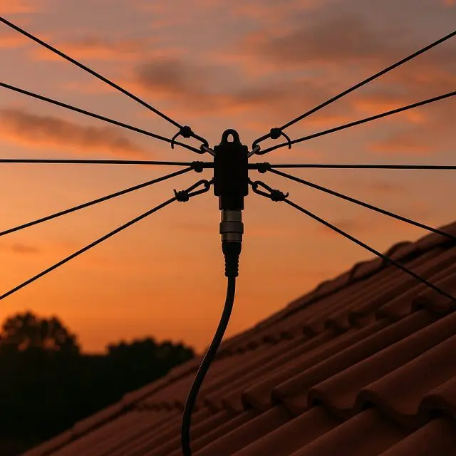
A fan dipole looks like a bundle of wires all meeting at the center insulator. Each pair is cut for a different band, and whichever pair resonates at the frequency you’re using will take the RF. It’s an elegant way to get multi-band coverage without a tuner. The downside? Interaction between wires can complicate tuning, and you might find yourself trimming more than once.
The Trap Dipole
A trap dipole takes a different approach, using little resonant LC circuits (traps) along each arm. On higher frequencies, the traps block RF so the antenna “looks shorter.” On lower frequencies, the traps pass RF so the full length resonates. This makes the antenna physically smaller for multi-band use. The price you pay is a bit of added loss and mechanical complexity.
The W3DZZ
The legendary W3DZZ antenna is a classic trapped dipole that covers 80 and 40 meters, and harmonics beyond. Generations of hams have used it successfully, but as with all trap antennas, good construction and careful tuning are critical.
End-Fed Half-Wave (EFHW) antennas
If there’s one antenna that has exploded in popularity over the last decade, it’s the End-Fed Half-Wave. Portable operators, QRP enthusiasts, and even home station builders love it. The idea is simple: instead of feeding a dipole in the middle, you connect your coax to one end of a wire that’s roughly half a wavelength long.
The trick, of course, is that the impedance at the end of a half-wave wire is extremely high—often 2–3 kΩ. That’s where the magic of the 49:1 or 64:1 unun comes in. This matching transformer steps down the impedance so your transceiver sees something close to 50 ohms.
An EFHW can cover multiple bands by simply cutting it for the lowest frequency and letting harmonics do the rest. For example, a 40-meter EFHW will also resonate on 20, 15, and 10 meters. Add a small counterpoise (something like 0.05–0.1 λ) and a good common-mode choke on the coax, and you’ve got yourself one of the most versatile antennas you can build.
People love EFHWs for SOTA (Summits on the Air) and POTA (Parks on the Air) because they can be tossed into a tree with a single support. They’re light, efficient, and quick to deploy.
Vertical antennas
While wire dipoles rule the rooftops and trees, vertical antennas are a favorite for DXers. Why? Because verticals naturally radiate at low angles, which helps your signal travel further before it skips off the ionosphere.
Quarter-wave verticals
The simplest vertical is a quarter-wave radiator standing straight up from the ground. To work properly, it needs radials—horizontal or sloping wires that act as the missing “half” of the antenna. With at least four radials (and ideally many more), the antenna is efficient and omnidirectional. A 7 MHz quarter-wave vertical, for instance, will need a radiator of about 10 meters and radials of similar length.
Five-eighths verticals
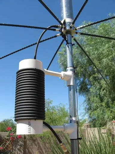
The 5/8-wave vertical is a little longer, and that extra length improves its low-angle radiation. It’s a favorite on VHF and CB radio, where DX performance is prized. The trade-off is that it no longer has a natural 50-ohm impedance, so you need a simple matching network (often a coil at the base).
Verticals are compact, they don’t need much horizontal space, and they excel at DX. The downside? Without enough radials, efficiency drops sharply, and nearby noise sources can be more noticeable than on a dipole.
Wire diameter, insulation, and shortening factors
Remember that neat formula for dipoles? It assumes thin, bare wire in free space. Real life looks different.
-
Wire thickness matters. Thicker wire tends to increase bandwidth. A fat conductor lowers the Q of the antenna, which means the SWR stays lower across a wider range of frequencies.
-
Insulation shortens the antenna. PVC-coated hookup wire, THHN, or even enamel-coated magnet wire have lower velocity factors than bare copper. That means the resonant length is shorter—sometimes by 3–5%.
-
Practical shortening factors. Even things like end insulators, knots, or bending the last bit of wire around a tree can make the antenna appear electrically longer. Many builders simply cut the wire a little long and trim in small steps during tuning.
So, while calculators give you an excellent starting point, the last few centimeters often come down to real-world fine-tuning.
Feedline considerations
An antenna is only as good as its feedline. If your coax eats half your signal, the best wire in the world won’t save you.
Coaxial cable
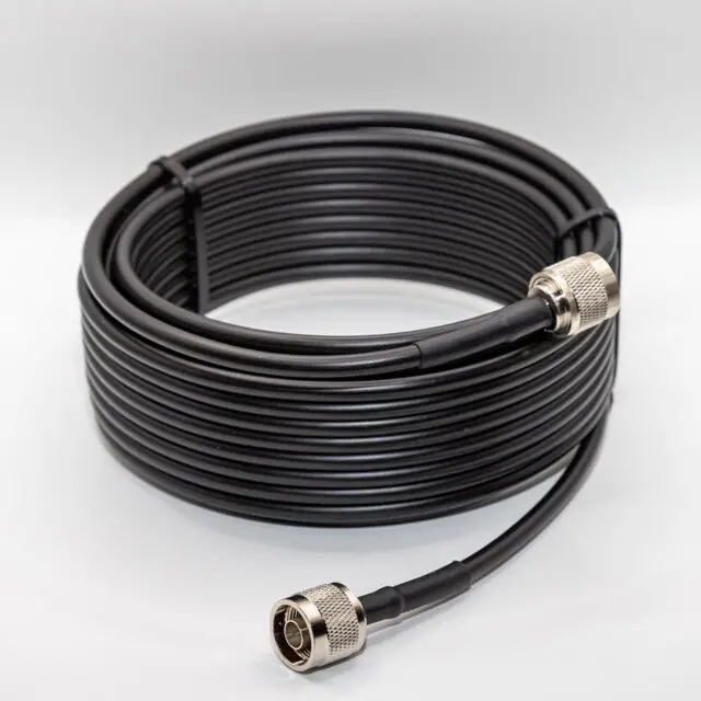
Coax is convenient, but it has losses that increase with both frequency and length. At HF, losses are modest, but at VHF/UHF they become critical. For example, 30 meters of RG-58 at 146 MHz can waste more than half your power. Heavier cables like RG-213 or LMR-400 are far more efficient but also bulkier.
Each coax also has its own velocity factor, typically around 0.66–0.85. This matters when you cut feedlines as phasing sections or quarter-wave stubs.
Ladder line
Balanced feedline, often called ladder line or open-wire line, has extremely low loss even over long distances. When used with a good antenna tuner, it allows non-resonant doublets to cover many bands efficiently. The catch? Ladder line must be kept clear of metal, gutters, and siding, or it will lose its advantage.
Matching and choking
Regardless of feedline type, choking common-mode currents is a good idea. A simple choke balun made from a few turns of coax on a toroid or air-wound coil can prevent RF from traveling where it doesn’t belong.
SWR, resonance and trimming
Sooner or later, every ham runs into the mysterious letters SWR. It stands for Standing Wave Ratio, and it’s basically a way of describing how well your antenna and feedline are matched to your radio. A perfect match is 1:1, but in the real world anything below 2:1 is usually good enough.
Why resonance helps
When your antenna is resonant at the frequency you’re using, its impedance is mostly resistive and close to what your coax and radio expect. That usually means low SWR and happy finals in your transceiver.
If the antenna is too long or too short, resonance shifts, and the SWR creeps up. That doesn’t mean your antenna won’t radiate—it will—but more of your power bounces back toward the transmitter instead of getting out.
How to trim an antenna
Here’s a practical truth that every builder learns: an antenna calculator gets you close, but the final adjustment happens with wire cutters in hand. The usual method is:
-
Cut your dipole or vertical a little longer than calculated.
-
Put it up at the planned height.
-
Measure the SWR at the frequency of interest.
-
If resonance is too low, trim small amounts from each side (symmetrically).
-
If resonance is too high, you may need to add a bit of wire back.
Don’t rush this process. Trimming 2–3 cm can make a noticeable shift at HF. At VHF, even a few millimeters matter.
Tools to make life easier
-
Antenna analyzers like the NanoVNA or RigExpert can show you the exact resonance and SWR curve.
-
Your rig’s SWR meter is a rougher tool, but it works.
-
Cut-and-try with patience is the oldest method and still reliable.
Practical tips for building wire antennas
Theory is nice, but the real fun comes when you’re hanging wires in the backyard, on a mast, or from a tree in the middle of nowhere. Here are some tips that can save you headaches:
-
Choose your wire wisely. Bare copper is efficient but stretches. Enameled or insulated wire is tougher. Stranded wire handles flexing better than solid wire.
-
Think about the weather. UV-resistant jacketed wire lasts much longer in the sun. Nylon cord for support will degrade outdoors; Dacron rope is a better investment.
-
Insulators matter. End insulators don’t just hold the wire—they slightly lengthen it electrically. Ceramic or plastic both work, just avoid metal near the wire ends.
-
Tension is key. Don’t pull the wire as tight as a guitar string. Leave a little slack for wind and temperature changes.
-
Portability counts. If you’re operating portable (SOTA, POTA, field day), lightweight wire and a simple winder can make setup and teardown fast and fun.
-
Use chokes and baluns. They might not look glamorous, but they keep RF out of the shack and make the antenna behave predictably.
Sometimes the best tip is: don’t overthink it. Get a wire in the air, tune it as best you can, and start making contacts. Perfection is nice, but contacts are what make the hobby rewarding.
What about noise?
One last thing worth mentioning: antennas don’t just transmit—they receive too. And not all environments are equal. If you live near power lines, solar inverters, or noisy electronics, your vertical may pick up more hash than a dipole. Sometimes simply rotating, raising, or moving your antenna a few meters can cut the noise dramatically. Experimenting is part of the process.
Frequently asked questions about antenna length and design
How do you calculate antenna length?
The simplest method is to divide 300 by the frequency in MHz, then adjust with a shortening factor. For a dipole, take half of that result and use it as the total length. For example, on 14.2 MHz, the total length is about 10.5 meters. But remember—insulated wire and installation height can make it a bit shorter in practice.
What is the best antenna for HF portable operation?
For many operators, the End-Fed Half-Wave (EFHW) wins. It requires only one support, works on multiple bands thanks to harmonics, and can be set up quickly in the field. Some prefer a lightweight dipole or an inverted-V, but for grab-and-go portable use, EFHWs are hard to beat.
How does wire thickness affect antenna performance?
Thicker wire tends to broaden the bandwidth of the antenna. That means the SWR stays lower across more frequencies. It doesn’t radically change efficiency, but it makes tuning less finicky. On the other hand, very thin wire is light and easy to pack, so there’s always a trade-off.
What is the velocity factor of coax?
Each coaxial cable has a velocity factor—how fast RF travels inside compared to free space. For RG-58, it’s about 0.66; for RG-213, around 0.67; and for foam-dielectric cables like LMR-400, closer to 0.85. This matters when you cut phasing lines, stubs, or tuned lengths of coax.
How do I tune a dipole without an antenna analyzer?
It can be done with just your rig and its SWR meter. Start with a slightly longer dipole than the formula suggests, raise it to operating height, and check the SWR. If the resonant point is below your target frequency, trim a bit of wire from each end. If it’s too high, add wire. Small adjustments—just a few centimeters—make a big difference.
Do I always need a balun?
Strictly speaking, a dipole will still radiate without one, but you’ll risk RF currents flowing back on the coax shield. That can cause RFI, distorted patterns, and sometimes even shocks at the radio end. A simple 1:1 current balun is cheap insurance for stable performance.
Can one antenna really cover all bands?
Yes and no. Multi-band antennas like fan dipoles, trap dipoles, EFHWs, and doublets with tuners all work across several bands. But each has trade-offs—efficiency, complexity, or size. The dream of one perfect antenna for every situation is just that: a dream. In reality, most operators keep two or three favorite designs and use whichever suits the day’s conditions.
What’s the easiest beginner antenna?
Without a doubt, the half-wave dipole. It’s cheap, forgiving, and teaches you almost everything you need to know about resonance, SWR, and trimming. Once you’ve built one dipole, every other antenna will make more sense.
Building antennas is part science, part adventure
Antenna length calculators are fantastic tools. They give you a solid starting point, saving hours of trial and error. But no matter how accurate the math, every installation is unique. The trees in your yard, the height of your mast, the type of wire you use, even the soil under your feet—all of it tweaks the final result.
The good news? That’s part of the fun. Radio is an experimental hobby, and antennas are where science meets creativity. A calculator gets you 95% of the way. The last 5% comes from listening to your rig, trimming a few centimeters here or there, and smiling when you hear that distant DX station come back to your call.
So, don’t be afraid to get some wire in the air. Try a dipole, experiment with an EFHW, play with a vertical. Use the calculator to guide you, but trust your ears and your logbook too. After all, the best antenna isn’t just the one with perfect math—it’s the one that gets you on the air, making contacts, and enjoying the magic of radio.
Image(s) used in this article are either AI-generated or sourced from royalty-free platforms like Pixabay or Pexels.
Did you enjoy this article? Buy me a coffee!


