Designing an efficient magnetic loop antenna requires precise calculations of loop dimensions, conductor diameter, and tuning capacitor values. This calculator helps you determine the key parameters for building a magnetic loop antenna for HF and VHF bands. Simply enter your desired frequency, loop diameter, and conductor size to get optimal values for inductance, capacitance, and estimated bandwidth. Ideal for amateur radio operators and RF hobbyists aiming for compact, high-efficiency antennas in limited spaces.
MagLoop Antenna Calculator
Understanding the Magnetic Loop Antenna
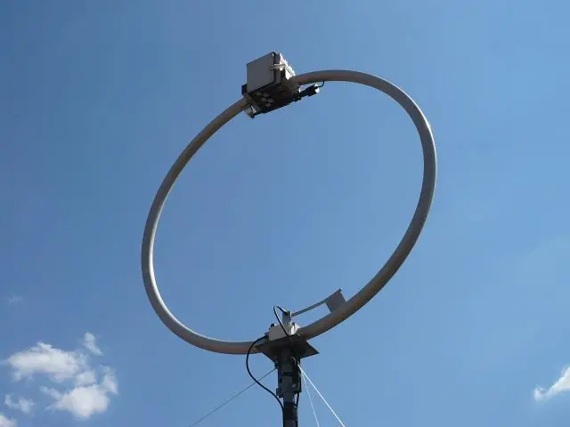
A magnetic loop antenna is a small transmitting loop antenna (STL) that operates efficiently on HF frequencies despite its compact size. Unlike traditional wire or vertical antennas, which are often full quarter- or half-wavelength structures, the magnetic loop operates as a resonant LC circuit, primarily coupling via the magnetic field.
In simple terms, the magnetic loop consists of:
-
A circular or polygonal conductor loop (usually copper or aluminum)
-
A tuning capacitor (often high-voltage, variable)
-
A feed loop or gamma match for coupling to the transceiver
Its most distinctive trait is its small physical size relative to the wavelength — often less than 1/10th of a wavelength — while still maintaining respectable efficiency under proper conditions.
Electromagnetic Behavior and Efficiency
Unlike electric-field dominant antennas, magnetic loops primarily utilize the magnetic component of the electromagnetic field near the loop, hence the name. Their efficiency depends heavily on factors such as:
-
Loop diameter
-
Conductor diameter
-
Frequency of operation
-
Quality (Q) of the capacitor
-
Radiation resistance vs. loss resistance
The radiation pattern is nearly omnidirectional in the horizontal plane and exhibits a deep null perpendicular to the plane of the loop — useful for rejecting unwanted signals or noise.
Benefits of Magnetic Loop Antennas
-
Compact Size: Ideal for small balconies, apartments, RVs, and portable operations.
-
Efficient for QRP: Especially valuable for low-power (QRP) operators seeking high field strength in compact setups.
-
High Signal-to-Noise Ratio: The loop’s directional null can significantly reduce man-made noise.
-
Broadband Reception: While tuned narrowly for transmit, loops often provide wide reception bandwidth.
-
Easy Deployment: No need for high masts, radial systems, or extensive guying.
Challenges and Limitations
-
Narrow Bandwidth: Often requires retuning with minor frequency changes, especially on lower bands.
-
High-Voltage Tuning: Tuning capacitors must handle thousands of volts across plates.
-
Mechanical Complexity: Precision in capacitor design and loop construction is crucial.
-
Limited Power Handling: High currents at resonance limit usable TX power unless robust components are used.
Design Parameters and Formulae
Designing a magnetic loop starts with setting the desired frequency range. From there, key parameters include:
-
Loop diameter (D): Larger diameters improve efficiency but reduce portability.
-
Conductor diameter (d): Thicker conductors reduce resistance and improve Q.
-
Capacitance (C): Calculated based on resonance formula f=12πLCf = \frac{1}{2\pi\sqrt{LC}}
-
Inductance (L): Depends on loop size and conductor properties.
Online calculators (such as the one on this site) help simplify this process and estimate:
-
Resonant frequency
-
Required capacitance for tuning
-
Voltage across the capacitor
-
Loop efficiency and bandwidth
Typical Construction Materials
-
Tubing: Copper tubing (3/8 to 1 inch) is preferred for its low resistance.
-
Capacitor: Vacuum variable capacitors are ideal; butterfly capacitors or homebuilt plate capacitors can also be used.
-
Coupling Loop: Often a small 1/5 diameter loop of coax or wire placed inside the main loop.
-
Frame: PVC, wood, or fiberglass frames provide structure.
For portable builds, lightweight aluminum loops and compact tuning boxes offer excellent mobility.
Tuning Methods
-
Manual Tuning: Simple, cheap, but may require frequent adjustment.
-
Remote Tuning: Using stepper motors or servo-controlled capacitors, especially for rooftop or attic installs.
-
Automatic Tuning: Advanced systems with microcontrollers detect SWR and adjust capacitors in real-time.
Applications and Use Cases
-
Urban Environments: Where HOA rules or neighbors restrict antennas.
-
Field Operations: Parks, SOTA (Summits on the Air), POTA (Parks on the Air).
-
Portable/QRP Operation: When backpacking, hiking, or emergency communication.
-
Stealth Antennas: Easily camouflaged in bushes, attics, or balconies.
-
EMI Mitigation: Reduced pickup of electric field noise in high-interference zones.
Real-World Performance
While magnetic loops have limited bandwidth, operators consistently report DX contacts from compact setups — even at QRP power levels. A well-built loop on 20 meters can work 5,000–10,000 km with 10 watts under good conditions.
Case studies show:
-
40m portable loops enabling Europe–North America contacts
-
30m indoor loops in apartments reaching intercontinental stations
-
20m QRP loops used in SOTA/POTA activations with <5W power
Installation Best Practices
Proper placement and installation can greatly influence performance:
-
Height Above Ground: Loops should be placed 1–2 meters above ground for NVIS (Near Vertical Incidence Skywave) or higher for DX.
-
Clear of Obstructions: Avoid placement near metal objects, walls, or wiring that could detune the loop.
-
Weatherproofing: Use sealed enclosures for tuning components if installed outdoors.
-
RF Ground: Not strictly required, but nearby conductive structures may impact tuning.
Tuning Tips and Tricks
-
Use an SWR Meter or Analyzer: Precisely tune for lowest SWR at target frequency.
-
Mark the Dial: If manual, mark key positions for each band to ease future retuning.
-
Consider Band-Switching Capacitors: For rapid QSY across multiple bands.
-
Use Shielded Coax for Coupling Loop: Reduces common mode currents and unwanted pickup.
Common Mistakes to Avoid
-
Too Small Loop Size: Below 0.1 wavelength reduces efficiency dramatically.
-
Thin Wire as Main Conductor: High resistance and increased loss.
-
Improper Capacitor Rating: Arcing and damage from RF voltages.
-
Poor Loop Symmetry: Irregular shape affects current distribution.
-
Neglecting Shielding or Ferrites: Leads to RF feedback and interference.
DIY Project: Building a Basic Magnetic Loop
Example for the 20-meter band:
-
Loop Diameter: 1 meter (3.28 feet)
-
Conductor: 3/4″ copper tubing, bent into a circle
-
Capacitor: 100–400 pF vacuum variable, rated for 5 kV
-
Coupling Loop: 20 cm loop made from RG-58 coax, inside main loop
-
Mounting: PVC frame or wooden base with insulation
Build steps:
-
Form the copper tubing into a loop and solder the ends to the tuning capacitor.
-
Attach the coupling loop at the bottom center.
-
Mount the assembly vertically on a non-conductive frame.
-
Connect the coupling loop to your transceiver via coax.
-
Tune for lowest SWR using a meter or antenna analyzer.
Optional: Add a rotor or remote tuning mechanism for convenience.
Magnetic Loop vs. Other Antenna Types
| Feature | Magnetic Loop | Vertical Antenna | Dipole |
|---|---|---|---|
| Size | Very compact | Medium to tall | Requires space |
| Tuning | Precise tuning | Often broadbanded | Usually broadbanded |
| Efficiency | High (small size) | Good (needs radials) | Excellent |
| Noise Rejection | High (directional) | Low | Medium |
| Portability | Excellent | Fair | Poor to fair |
| Build Complexity | Medium to high | Low to medium | Low |
Future Trends and Developments
With the rise of digital modes like FT8 and JS8Call, and increased urban density, magnetic loop antennas are gaining popularity as a solution for efficient, low-noise, low-profile HF operation. Innovations include:
-
3D-printed loop frames and capacitor housings
-
SDR-integrated automatic tuning
-
Smart antennas with app-controlled tuning
-
Compact loops for 6m and 2m operation
Communities such as Reddit’s /r/amateurradio, QRZ forums, and dedicated YouTube creators regularly showcase new loop builds, tuning techniques, and performance tests. Interest in loops continues to rise in emergency preparedness groups, van-lifers, and stealth operators who need discretion without sacrificing signal reach.
Magnetic loop antennas offer a unique balance of performance, size, and noise rejection. For those with limited space or looking to operate portable and QRP, a well-designed MLA can rival much larger systems. With proper construction and tuning, they deliver serious capabilities in a surprisingly small footprint.
Whether you’re a seasoned ham radio operator or a curious experimenter, exploring magnetic loop antennas opens the door to efficient HF communication in the most challenging environments.
Image(s) used in this article are either AI-generated or sourced from royalty-free platforms like Pixabay or Pexels.
Did you enjoy this article? Buy me a coffee!


