Why the AGC is iconic
The Apollo Guidance Computer (AGC) was not just a contemporary computer; it embodied an entire design philosophy. It was created for an environment where failure had an immeasurable cost, resources were scarce, and software updates were essentially “hardwired” into core rope memory. This forced a discipline in hardware and software design that remains relevant today in embedded systems, robotics, aerospace, and real-time control. In this article we will examine the AGC in detail: word format, register set, memory organization, bank switching, I/O and the DSKY interface; the Executive/Waitlist scheduling system; the famous 1201/1202 alarms; and finally compare its capacity and architecture with today’s smartwatches and smartphones.
Physical and environmental requirements
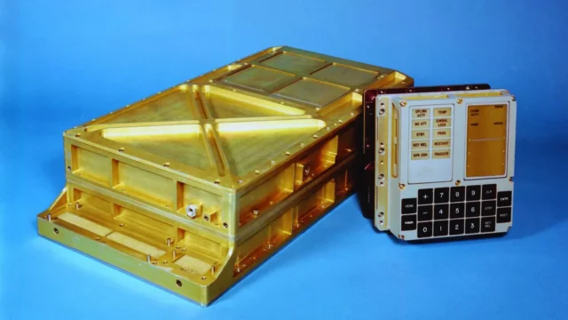
The AGC was installed both in the Command Module (CM) and Lunar Module (LM), designed to withstand the harsh conditions of space: vibration, temperature extremes, vacuum, radiation, and electromagnetic interference. The complete system weighed about 30–32 kg and consumed roughly 50–60 W. Its modular construction used soldered cards and standardized connectors to minimize mechanical failure points. The goal: compact volume, stable thermal management, easy servicing, and quick diagnostics.
Integrated circuits and logic: the “all NOR” philosophy
The Block II generation’s key feature was the use of silicon integrated circuits in volume. The logic family was RTL (Resistor-Transistor Logic) based on 3-input NOR gates. NOR is a universal gate: any Boolean function can be built from it. The CPU core—ALU, control logic, multiplexers, state machines—was designed entirely around this single gate type. This simplified production, stocking, and quality assurance, and statistically improved MTBF (mean time between failures). Fewer packages, fewer solder joints, fewer opportunities for defects—one of the AGC’s hidden advantages.
Word format and arithmetic
The AGC used a 16-bit word, of which 15 bits were data and 1 bit was parity. The parity bit provided error detection; arithmetic used 1’s complement with a dedicated overflow bit. This was simple, deterministic, and well suited to the technology of the time. Fixed-point representation avoided the need for expensive floating-point hardware, and algorithms (navigation, control, filtering) were reformulated to fit fixed-point math.
Register set and instruction set
The programmer’s view centered on a few key registers:
-
A – accumulator, result register of the ALU
-
Z – program counter (PC)
-
Q – division remainder / control transfer return
-
LP – lower product word of multiplication
The instruction set was compact (about three dozen opcodes) but tailored to the mission. Simple ALU operations were fast, memory-intensive or multiply/divide operations slower. Execution times ranged from 10 to 100 µs, giving an overall throughput of tens to hundreds of thousands of instructions per second. Far more important than raw speed was the careful scheduling and predictable jitter.
Clock and timing
The system used a 2.048 MHz quartz reference divided down to a 1.024 MHz four-phase internal clock, driving CPU state machines, memory access, and the interrupt system. Lower-frequency ticks (around 100 Hz) were derived for real-time counters and periodic tasks. This deterministic timing guaranteed that the GN&C (Guidance, Navigation & Control) loops ran with consistent delays.
Memory architecture: core RAM and rope ROM
The erasable memory was magnetic core RAM, 2,048 words (about 4 kB). The fixed memory was the legendary core rope ROM, around 36,864 words (about 74 kB). Rope ROM bits were literally woven wires: a wire threaded through a core represented a 1, bypassing represented a 0. Software was therefore “hard-wired” at manufacture. The result: extremely strict build and QA procedures, since modifying flight software was almost impossible once built.
Bank switching and code discipline
The 12-bit effective address field required bank switching to access the full memory space. RAM was organized into 256-word pages, ROM into larger banks. A strict “bank hygiene” programming style was enforced: calling conventions, jumps, returns, macros, and link rules ensured execution always landed in the correct bank. In embedded design, this discipline is still comparable to modern memory windows and peripheral paging.
I/O system and peripherals
The AGC communicated via I/O channels with:
-
IMU (Inertial Measurement Unit): gyros and accelerometers with drift compensation and alignment procedures
-
Radars: landing radar and rendezvous radar in the LM
-
Engine control: main engine and RCS (Reaction Control System thrusters)
-
Telemetry and uplink: state and command data exchange with Earth
-
DSKY: the Display & Keyboard, the crew interface
I/O channels transferred 15-bit words with redundancy, parity, and strict timing, ensuring sensor data and control commands arrived deterministically.
DSKY: the Verb–Noun interface
The DSKY (Display and Keyboard) was an early example of purposeful user interface design. Commands were entered as Verb (action) and Noun (object) pairs (e.g., Verb 06 Noun 20: display a particular state vector). The display had three five-digit electroluminescent readouts plus status lights (PROG, UPLINK ACTY, etc.). The command language was compact, consistent, and easily memorized—ideal under stress, minimizing crew workload. The CM carried two DSKY units, the LM one.
Real-time operating system: Executive and Waitlist
The key software component was the Executive, a priority-driven, preemptive scheduler. Critical GN&C tasks received the highest priority, while less urgent tasks were placed on the Waitlist. In overload situations, the Executive discarded lower-priority jobs and ensured only the most critical loops continued. This protective mechanism allowed the system to stay stable under extreme load.
The 1201/1202 alarms explained
During Apollo 11’s landing, 1201/1202 alarms indicated Executive overload. Extra interrupts from the rendezvous radar pushed the CPU beyond its nominal load. The system responded as designed: critical control loops continued, while non-essential tasks were dropped or delayed. Key navigation data was preserved across resets. This was not a crash but a deliberate fail-operational response—a triumph of system design under stress.
Guidance and control: sensor fusion, Δv, DAP
The software continuously integrated IMU data (rates and accelerations), corrected with drift models and periodic realignment. The CM optics (sextant, telescope) provided star references, while LM radars added measurements. Sensor fusion was carried out in fixed-point math. For trajectory changes the AGC computed required Δv, burn times, and profiles; the DAP (Digital AutoPilot) generated actuator commands for engines and RCS.
Software lines: Colossus and Luminary
The CM software was Colossus, the LM’s was Luminary. Both were written in AGC assembly, with strict conventions, verbose comments, and modular style. Rope ROM’s long manufacturing lead meant releases were rare but highly stable; last-minute changes were essentially impossible, so preventive quality assurance was the rule.
Development and QA chain
Source code was assembled on ground-based mainframes with special assemblers and simulators (IMU and DSKY emulators). The build produced a “weaving list” for rope ROM manufacture, followed by multi-stage electrical, functional, thermal, and vibration testing. Coding discipline here was not just style—it was mission assurance.
Performance in numbers
-
Word length: 15 data bits + 1 parity
-
RAM: 2,048 words (~4 kB)
-
ROM: ~36,864 words (~74 kB)
-
Clock: 2.048 MHz reference → 1.024 MHz internal
-
Instruction times: ~10–100 µs
-
Throughput: tens to hundreds of thousands of instructions/s
-
Power consumption: ~50–60 W
-
Mass: ~30–32 kg
By modern standards this is microcontroller-level performance—yet this “microcontroller” accomplished the most demanding real-time control task ever flown.
Reliability and fault tolerance
Reliability was achieved through multiple layers:
-
Parity on every word
-
Watchdog/reset with protected state data
-
Priority protection: critical tasks always ran even under overload
-
Physical robustness: space-rated manufacturing and testing
-
Simplicity: small codebase, few opcodes, fewer “moving parts” in hardware and software
Why no floating-point unit?
Most tasks were reformulated for fixed-point math with proper scaling. The AGC engineers preferred “mathematics on the drawing board”: avoiding floating point whenever possible, and emulating it in software only when absolutely necessary.
“Was it weak?” – putting it in context
The popular phrase “your phone is thousands of times more powerful” is true in raw MIPS but misleading in purpose. Smartphones optimize for average latency, multimedia, networks, AI, and sandboxed apps; the AGC provided deterministic RT guarantees, with planned scheduling and strict priorities. It was not faster—it was predictable, where lives depended on it.
Comparison with modern smart devices
Raw resources
-
AGC: ~0.1 MIPS, ~4 kB RAM, ~74 kB ROM, ~1 MHz internal clock
-
Smartwatch: multicore 1–2+ GHz CPU, 1–2 GB RAM, 8–64 GB flash, often with DSP/NPU
-
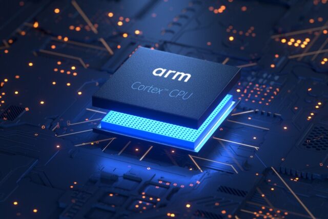
Smartphone: big.LITTLE architecture, 3+ GHz cores, 6–16 GB RAM, 128 GB–1 TB storage, powerful GPU/NPU
The ratio is in the thousands to millions. But the AGC’s job was not to run a multitude of apps; it was to guarantee a handful of critical loops.
Instruction set and programmability
The AGC offered a small ISA, manual bank switching, and fixed-point mindset. Today’s devices run 64-bit ISAs, out-of-order execution, SIMD, JIT, and high-level languages. Developer productivity is vastly higher—but RT guarantees often require separate RTOS layers or microcontrollers alongside.
Real-time and jitter
The AGC was deterministically timed. Modern SoCs are optimized for throughput and average response; jitter control is handled with isolated cores, RT priorities, or companion MCUs (e.g., always-on sensor hubs).
Energy and heat
Technology nodes are incomparable; per operation, modern SoCs are orders of magnitude more efficient. But their scope is far broader. The AGC consumed ~50–60 W under well-defined workloads—a rational design point within the spacecraft’s power budget.
Reliability and updates
AGC rope ROM was immutable, verified to the extreme. Phones and watches receive OTA updates, flexible but harder to formally prove safe—yet defects can be patched quickly, and features evolve.
Systems engineering lessons for today
-
Ruthless priority management: the critical loop must always win
-
Deterministic timing: known jitter profiles and guaranteed execution windows
-
Memory discipline: bank switching, modular boundaries, strict conventions
-
Fail-operational mindset: reset is not failure if state retention is designed in
-
Simplicity and QA: fewer gate types and ICs → easier manufacturing and testing
Common misconceptions
-
“The AGC was just a pocket calculator.” Its raw MIPS were low, but its deterministic reliability was on a completely different level.
-
“The 1201/1202 nearly doomed Apollo 11.” In fact, the alarms showed the protective design working: critical loops ran, non-critical tasks dropped, astronauts stayed in control.
Quick data sheet
-
Developer: MIT Instrumentation Lab / Raytheon
-
Architecture: RTL NOR-logic, 16-bit word (15 data + 1 parity)
-
Memory: 2 k words RAM, ~36 k words rope ROM
-
Clock: 2.048 MHz reference → 1.024 MHz internal
-
OS: Executive/Waitlist, preemptive priority-based RT scheduler
-
UI: DSKY Verb/Noun, electroluminescent displays, status lights
-
Peripherals: IMU, radars (LM), RCS/engine, telemetry, uplink
The Apollo computer’s story is not about “how little it could do” but about how exactly enough it did, with astonishing reliability. Engineers relied on strict simplicity, disciplined memory and timing, and rigorous testing. In the tense moments of the 1201/1202 alarms, the system’s strength—not its weakness—was revealed: the AGC did exactly what it was designed for, protecting the mission. Today we lean on raw performance in our phones and watches, but the AGC reminds us that good architecture and real-time discipline are irreplaceable. This “less but certain” philosophy took humanity to the Moon—and still makes the difference between a prototype that works sometimes and a system that works every time.
Image(s) used in this article are either AI-generated or sourced from royalty-free platforms like Pixabay or Pexels.
Did you enjoy this article? Buy me a coffee!


