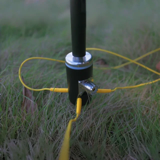
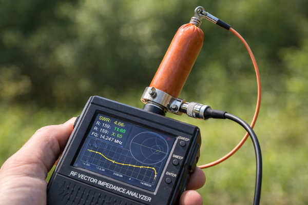
There are few phrases in the antenna world that sound as seductive, and as suspicious, as radial-less antenna. To a radio amateur fighting with a cramped backyard, a CB user mounting an antenna on fiberglass, a sailor trying to get reliable VHF coverage from a plastic boat, or a portable operator who wants to be on the air before sunset, the promise feels almost magical. A vertical antenna with no ground radials. No copper wires spread across the lawn. No carefully tuned counterpoise lines. No buried radial field. No metal roof. No elaborate ground plane. Just mount the antenna, connect the coaxial cable, check the SWR, and start transmitting. Anyone who has ever tried to make a quarter-wave vertical work properly on the lower HF bands understands why that promise is so attractive. The classic vertical antenna seems to demand a missing half: the ground, the radials, the counterpoise, the conductive surface against which the radiating element can work. When a manufacturer appears to make that requirement disappear, the obvious question follows: is this radio-frequency magic, a marketing trick, or a legitimate engineering compromise?
The honest answer is that a radial-less antenna is not magic, but neither is it automatically a scam. In most cases, the missing counterpoise has not disappeared; it has been moved, hidden, shortened, transformed, integrated into the antenna body, borrowed from the feed line, or replaced by a different radiating structure. The laws of electromagnetism do not offer an exemption for convenient product names. A transmitting antenna still needs an RF current distribution. It still produces electric and magnetic fields. It still interacts with its surroundings. It still requires some form of return path, opposing conductor, displacement current, or balanced structure that allows energy to leave the transmitter and become a propagating radio wave. The real question is not whether the antenna has a “second half,” but where that second half is, how much loss it introduces, how predictable it is, and whether the user has any control over it.
This is what makes radial-less antennas so fascinating. They occupy the borderland between elegant physics and practical necessity. In textbooks, a vertical antenna over a perfect conducting ground plane is clean, symmetrical, and easy to analyze. In real life, antennas are attached to vehicles, balconies, sailboats, rooftops, masts, handheld radios, military packs, RVs, fiberglass poles, metal railings, and improvised field installations. The earth is not a perfect conductor. Buildings are full of wiring and noise. Coax shields can become unintended radiators. A metal gutter can become part of the antenna system without ever being invited. Under these conditions, the phrase “no radials required” may mean many different things. It may describe a genuinely self-contained design, a half-wave radiator that depends less on a ground plane, a sleeve dipole hidden inside a vertical tube, a loaded antenna with internal matching, or a system that quietly relies on the coax shield and surrounding objects to complete the job.
That ambiguity is why radial-less antennas provoke strong opinions. Some operators swear by them because they solve real installation problems and make reliable communication possible where a conventional ground-plane antenna would be impractical. Others dismiss them as lossy compromises dressed up in advertising language. Both reactions can be correct, depending on frequency, design, installation, and expectations. A radial-less VHF antenna on a fiberglass boat can be an excellent and entirely sensible choice. A heavily shortened radial-less vertical for 80 meters can also work, but its efficiency may be far below what its pleasant SWR reading suggests. A UHF no-ground-plane antenna may be compact and convenient, yet still sensitive to coax routing, mounting brackets, and nearby metal objects. The story changes across HF, VHF, and UHF because wavelength changes everything: size, loss, feed-point behavior, coupling, bandwidth, and environmental sensitivity.
The Missing Half of the Antenna
To understand why radial-less antennas are both possible and limited, it helps to begin with the most familiar antenna of all: the half-wave dipole. A center-fed dipole has two conductive arms. RF current flows in one direction on one side and in the opposite direction on the other. The electric and magnetic fields form around the complete structure, and energy is radiated into space. The dipole is not mysterious because its symmetry is visible. You can point to one half, then the other, and see the complete antenna system. A quarter-wave vertical is more subtle. It looks like a single upright conductor, but it is usually intended to operate against a ground plane. In the idealized version, the ground acts like a mirror. The vertical element above the ground and its image below the ground behave much like a complete half-wave antenna.
The problem is that real ground is not an ideal mirror. Dry soil, wet clay, salt marsh, rooftop concrete, a vehicle roof, a steel ship deck, and a rocky mountain summit all present different electrical environments. At HF, where wavelengths are long and vertical antennas can be physically large, ground loss becomes a dominant issue. A quarter-wave vertical for 40 meters is roughly ten meters tall. On 80 meters, it is about twenty meters. If such an antenna is placed directly on poor earth with few or no radials, a significant portion of transmitter power can be lost as heat in the soil and nearby conductors instead of being radiated as useful RF energy. The transmitter may still see an acceptable impedance. The SWR meter may still look reassuring. But low SWR does not prove high efficiency. A dummy load also has excellent SWR, and it is famous precisely because it does not radiate well.
Radials provide a controlled, low-loss return path for RF current. They reduce the amount of current forced through lossy soil. They stabilize feed-point impedance. They make the radiation pattern more predictable. In a classic ground-mounted vertical, the radial system is not a decorative accessory; it is part of the antenna. The more carefully it is designed, the less the surrounding ground dominates the system. When the radial system is removed, something else must take over its role. That something may be a short counterpoise, an elevated conductor, a metal vehicle body, the coax shield, a mast, a capacitive coupling to earth, or an internal antenna section engineered to provide the missing electrical function. The physics does not vanish. It simply becomes less visible.
This distinction matters because the word radial-less can mislead. A better phrase in many cases would be external-radial-less. The antenna may not require separate wires extending from its base, but it may still contain an internal counterpoise, sleeve, matching section, coaxial structure, or balanced radiator. In other cases, the antenna may not contain a sufficient counterpoise at all and may instead depend on whatever conductive objects are attached or nearby. The first kind of design can be highly repeatable and well engineered. The second kind may still work, sometimes surprisingly well, but its performance can vary dramatically from one installation to another. A radial-less antenna that behaves differently when the coax length changes is telling you something important: the feed line is part of the antenna system.
The deeper truth is that antennas are not isolated objects. They are systems. The radiating element, matching network, feed line, mounting structure, ground environment, nearby conductors, and even the operator’s body can all influence performance. This is especially clear with handheld VHF and UHF radios. A rubber-duck antenna mounted on a handheld transceiver often uses the radio chassis, battery pack, microphone cable, and the user’s hand and body as part of its effective counterpoise. The antenna may be sold as a single replaceable object, but electrically it is only one portion of a larger radiating system. The same principle appears in larger forms across HF, VHF, and UHF. The “missing” part is rarely missing. It is simply distributed through the installation.
Why the Radial-Less Idea Became So Appealing
The appeal of radial-less antennas is rooted in a very real frustration. Most people do not operate from ideal antenna farms. They operate from apartments, balconies, small gardens, vehicles, temporary campsites, boats, emergency communication stations, rented houses, suburban lots, and portable field locations. In those places, the textbook radial field can be physically impossible, socially unacceptable, or simply too much work. A web of wires across the lawn may trip family members, annoy neighbors, interfere with mowing, invite corrosion, or violate rental restrictions. Elevated radials may need supports that cannot be installed. A metal ground plane may not exist. Even when the operator understands antenna theory perfectly, practical life often refuses to cooperate.
Manufacturers understand this pain point. The phrase no ground plane required or radial-less vertical antenna speaks directly to it. It promises speed, simplicity, and freedom from one of the messiest parts of antenna installation. In many applications, that promise has genuine value. A marine VHF antenna mounted on a fiberglass sailboat cannot rely on a car roof. A motorhome antenna may need to operate from nonmetallic bodywork. A portable HF operator may want an antenna that can be raised on a telescoping pole without spending half an hour arranging radials. A public-safety or military user may need rapid deployment under conditions where textbook efficiency is less important than communication happening at all. Convenience is not a trivial feature. An antenna that can actually be installed is often better than a theoretically superior antenna that remains in the garage.
The trouble begins when convenience is mistaken for free performance. Every antenna design trades among size, efficiency, bandwidth, radiation pattern, impedance behavior, mechanical strength, cost, and environmental tolerance. A radial-less antenna shifts those trade-offs toward ease of installation. The cost may be reduced efficiency, increased matching loss, narrower usable bandwidth, stronger common-mode current on the coax, greater sensitivity to nearby objects, higher receive noise, or a radiation pattern that differs from expectations. Sometimes the cost is small and entirely acceptable. Sometimes it is large. The difficulty is that the cost is not always visible on an SWR meter, and it may not be obvious until the antenna is compared with a reference system under real conditions.
The marketing language also compresses several different technologies into one phrase. A radial-less HF vertical, a no-ground-plane VHF marine antenna, a half-wave mobile whip, a sleeve dipole, an end-fed wire, a J-pole, and a compact UHF collinear antenna may all be described in similar consumer language, even though they operate in different ways. This creates confusion. Some designs genuinely incorporate their own electrical balance. Others reduce ground dependence but do not eliminate environmental interaction. Others are simply short loaded monopoles that rely heavily on whatever conductive mass is available. Without looking at the actual construction and use case, the label tells only part of the story.
This is why experienced antenna builders tend to ask practical questions rather than argue about the name. What band is it for? Is it electrically a quarter-wave, half-wave, end-fed, sleeve, collinear, loaded whip, or something else? Where is the matching network? Does the coax need to be a certain length? Does the manufacturer recommend a choke? Does performance change when the antenna is moved away from metal? What happens to SWR and noise when a counterpoise is added? Does the antenna heat up at power? These questions cut through the mythology. They reveal whether the radial-less claim is a sign of thoughtful engineering or merely a way to make a compromise sound miraculous.
HF Radial-Less Antennas: Where the Ground Sends the Bill
HF is where the radial-less promise becomes most tempting and most dangerous. The lower the frequency, the larger the wavelength and the more painful a proper radial system becomes. On 80 meters, a quarter-wave vertical is roughly twenty meters tall. On 40 meters, it is around ten meters. Even on 20 meters, a full-size vertical is still a significant structure. The radials required for a highly efficient ground-mounted vertical consume space, wire, effort, and patience. In a small garden or urban environment, a large radial field may be impossible. This is exactly the environment in which radial-less HF verticals and end-fed systems become attractive.
Many HF radial-less antennas are based on some version of the end-fed concept. A wire or vertical element is fed at or near one end rather than in the center. If the radiator is close to a half-wavelength on the operating frequency, the feed-point impedance may be high. A transformer, unun, or matching network converts that impedance to something the transmitter and coax can tolerate. Because the current at the feed point may be lower than in a quarter-wave monopole, the need for a large ground plane can appear reduced. This is why end-fed half-wave antennas are so popular for portable HF operation. They can be quick to deploy, physically simple, and capable of excellent real-world contacts.
But end-fed does not mean counterpoise-free in the absolute sense. The matching unit has two terminals from an RF perspective, even if one of them is not obvious. Some current must flow somewhere outside the main radiator. That current may use a short counterpoise wire, the outside of the coax shield, the radio chassis, a support mast, capacitive coupling to the environment, or a mixture of all of these. If the designer provides a defined counterpoise or includes adequate choking, the system can be controlled. If not, the coax may become an unintended part of the radiating structure. This can improve apparent performance in some cases, but it also makes the antenna installation-dependent. Change the coax length, move the radio, add a USB cable, touch the microphone, and the system may behave differently.
Loaded HF verticals present another set of compromises. A physically short antenna can be made resonant with loading coils, traps, capacitance hats, or matching networks. These techniques are legitimate and widely used, but they carry losses. A short vertical on a low HF band may have a very small radiation resistance. If the radiation resistance is only a few ohms, then even a few ohms of loss in the coil, ground system, matching network, or nearby environment can consume a large fraction of the transmitted power. The antenna can still be tuned. The SWR can still look good. But the efficiency may be poor. This is one of the great illusions of compact HF antennas: matching is not the same as radiating.
The problem becomes more severe as the antenna becomes shorter relative to wavelength. A small radial-less vertical for 80 meters may be easy to install, but it is fighting harsh physics. The loading coil may carry high current. The voltage at some points may be high enough to stress insulation. Bandwidth may be narrow because the system has a high Q. Nearby objects may detune it. Rain, soil moisture, and mounting height may alter performance. None of this means the antenna is useless. It may be the only practical way to get on the band from a restricted location. But the operator should understand what is being traded. On low HF, compact radial-less antennas are often about achieving usable communication, not maximum efficiency.
Higher HF bands are more forgiving. On 20, 17, 15, 12, and 10 meters, the physical size of efficient verticals becomes more manageable. A half-wave vertical can be raised on a fiberglass pole. A small counterpoise may be sufficient to stabilize the feed. A well-designed matching transformer can perform efficiently if built with appropriate cores and voltage spacing. A common-mode choke can keep the coax from becoming an uncontrolled radiator. Under good propagation conditions, such an antenna can make impressive DX contacts. This is one reason operators report excellent results with radial-less or minimal-counterpoise antennas. The success is real, but it is not supernatural. The antenna is operating in a frequency range where the compromise is less severe, and the propagation may reward even modest radiated power.
For HF operators, the most practical attitude is neither blind faith nor automatic dismissal. A radial-less HF antenna should be treated as a complete RF system whose boundaries need to be understood. Adding a short counterpoise may improve stability. Installing a high-quality common-mode choke at the feed point or along the coax may reduce shack RF and receive noise. Testing different mounting heights may reveal a better radiation angle. Comparing signal reports against a reference antenna may expose hidden losses. Watching whether SWR changes with coax routing can reveal common-mode current. The antenna may still be called radial-less, but the operator who understands its current paths will get better results than the operator who treats it as a sealed magical object.
VHF and UHF: Smaller Wavelengths, Different Compromises
At VHF and UHF, radial-less antennas become more plausible as self-contained designs because the wavelengths are much shorter. On the 2-meter amateur band, a quarter-wave is roughly half a meter. On the 70-centimeter band, it is around seventeen centimeters. A ground-plane antenna for these bands can be physically compact. Four sloping radials for VHF are not a backyard-consuming project, and UHF radials can be small enough to fit into a modest mechanical assembly. Because the dimensions are manageable, engineers can integrate the missing electrical structure into the antenna itself more easily than they can on low HF. This is why no-ground-plane VHF and UHF antennas are common and often quite effective.
One of the most common approaches is the half-wave vertical. A half-wave radiator does not require the same kind of large ground plane as a quarter-wave monopole because its current distribution is different. It is often fed through an impedance-matching network because the feed-point impedance can be high, especially when fed at the end. Once matched properly, it can operate well on fiberglass, plastic, or other nonmetallic surfaces. This is why half-wave VHF antennas are popular for marine use, RVs, and installations where a metal ground plane is unavailable. The antenna is not independent of physics; it simply uses a radiating structure that is less dependent on a conductive surface beneath it.
Another elegant solution is the sleeve dipole or coaxial dipole. From the outside, it may look like a simple vertical rod inside a fiberglass tube. Internally, however, the lower sleeve or coaxial section acts as the other half of the antenna. The feed line enters the structure in a way that encourages the desired RF current distribution while discouraging unwanted current on the outside of the coax shield. To the user, there are no visible radials. To the engineer, the antenna is a compact dipole-like system. This distinction is important because a well-designed sleeve antenna is not “missing” its counterpoise. It has integrated it. That is very different from a design that simply hopes the coax will take care of the problem.
The J-pole is another antenna often perceived as radial-less. It consists of a half-wave radiator fed through a quarter-wave matching section. It can be built from metal tubing, ladder line, or other conductors, and it does not require horizontal radials in the usual ground-plane sense. Yet it is not an antenna that escapes balance or return currents. The matching section and radiator together form the complete system. In practice, J-poles can still produce common-mode current on the feed line if not properly choked or constructed. Many operators discover that adding a choke below the feed point improves repeatability and reduces RF on the coax. Again, the theme repeats: no visible radials does not mean no RF management.
UHF raises a different set of concerns. Because the wavelength is short, small mechanical details become electrically significant. A connector, mounting screw, mast clamp, coax bend, bracket, or nearby metal rail can be a meaningful fraction of a wavelength. A radial-less UHF antenna can work very well, but it may also be more sensitive to installation geometry than users expect. The radiation pattern may be distorted by a metal mast, wall, roof edge, vehicle frame, or nearby cable. Coax loss also becomes more serious as frequency rises. An efficient antenna connected through a long run of poor coax may perform worse than a modest antenna fed with low-loss cable. At UHF, the antenna itself is only one piece of the link budget.
Handheld radios provide the most familiar example of hidden counterpoise behavior. A small VHF/UHF handheld antenna rarely works alone. The radio body, battery, speaker-microphone cable, operator’s hand, and operator’s body all influence the system. This is why handheld performance changes when the radio is held differently, placed on a table, clipped to a belt, connected to an external microphone, or used near a window. A longer aftermarket antenna may improve range because it is closer to an efficient electrical length, but it still interacts with the radio and user. Calling it radial-less is not entirely wrong from a consumer viewpoint, but electrically the antenna is still participating in a larger, messy system.
In mobile VHF and UHF installations, the difference between ground-plane and no-ground-plane antennas is especially practical. A quarter-wave whip on a metal car roof can perform very well because the vehicle body acts as a ground plane. Put the same antenna on a fiberglass vehicle body or a mirror bracket with poor bonding, and performance may suffer. A no-ground-plane antenna designed for such conditions can be the better choice because it includes the necessary electrical structure internally. On the other hand, if a large, well-bonded metal surface is available, a conventional antenna may be more efficient, simpler, and cheaper. The right answer depends less on ideology than on the actual mounting environment.
The Feed Line: Silent Partner or Unwanted Radiator
The coaxial cable is often the hidden character in the radial-less antenna story. In normal operation, RF current flows on the center conductor and on the inside surface of the shield. These equal and opposite currents create fields mostly confined within the cable, allowing the coax to act as a feed line rather than an antenna. But current can also flow on the outside surface of the shield. This is common-mode current, and it is no longer safely contained inside the cable. The outside of the coax can radiate, pick up noise, alter the antenna pattern, and carry RF back into the shack.
Radial-less and end-fed antennas are especially prone to this because their feed points are often unbalanced or poorly defined. If the antenna does not provide a clear return path or counterpoise, the coax shield may become the easiest available path. The result can look successful at first. SWR may improve. Signals may be heard. Contacts may be made. But the system may be unstable. Move the coax, coil it differently, add a laptop cable, or touch the radio, and the antenna changes. The operator may experience RF burns, distorted transmitted audio, computer interference, erratic tuner behavior, or high receive noise. These are classic symptoms of a feed line that has become part of the antenna system in an uncontrolled way.
A common-mode choke is one of the most useful diagnostic and corrective tools in this situation. A choke presents high impedance to current flowing on the outside of the coax shield while allowing normal differential-mode feed-line current to pass. When placed at the right location, often near the feed point, it helps define the boundary between antenna and feed line. If inserting a choke radically changes SWR or signal strength, it suggests that the coax was previously doing significant radiating or counterpoise work. That does not automatically mean the old setup was unusable, but it does mean the antenna was not truly self-contained. Understanding this can prevent endless confusion.
The location and design of the choke matter. At HF, ferrite material selection, number of turns, coax type, power level, and frequency range all influence effectiveness. A choke that works well on 20 meters may be inadequate on 80 meters or lossy at high power. At VHF and UHF, construction becomes more geometry-dependent, and ferrite or sleeve-style solutions must be appropriate for the band. The goal is not to add hardware blindly, but to control RF currents deliberately. In many radial-less systems, a good choke is the difference between a predictable antenna and a station-wide experiment.
There is also a philosophical point here. Some antenna systems intentionally use part of the feed line as a counterpoise. Portable operators sometimes exploit this successfully. A short coax run hanging from an end-fed antenna can serve as a convenient return path. In a temporary QRP setup, this may be entirely acceptable. But it should be understood as part of the design, not mistaken for the absence of a counterpoise. Once power increases, noise matters, or installation repeatability becomes important, the uncontrolled feed line becomes less attractive. The best radial-less designs either integrate the necessary structure or clearly specify how the feed line should be managed.
SWR, Efficiency, and the Great Antenna Illusion
The standing wave ratio has become the most visible number in everyday antenna work, but it is also one of the most misunderstood. SWR tells the operator how well the transmitter, feed line, and load impedance are matched at a particular point. It does not directly tell how much power is radiated. A perfect 1:1 SWR can describe an excellent antenna, a dummy load, or a lossy network that converts RF power into heat. This distinction is crucial when evaluating radial-less antennas because many designs include matching networks, loading coils, transformers, or environmental losses that can make the transmitter happy without making the antenna efficient.
Efficiency is the ratio of radiated power to power delivered to the antenna system. Loss can occur in soil, coils, traps, ferrite cores, resistive conductors, poor connections, lossy dielectric materials, matching networks, feed lines, and nearby objects. On HF, especially with shortened antennas, these losses can be large compared with the radiation resistance. A small vertical may be easy to match precisely because loss resistance broadens the impedance curve and masks the difficulty. The operator sees a wide usable SWR bandwidth and assumes the antenna is excellent. In reality, part of that bandwidth may come from loss. A highly efficient small antenna is often narrowband; a suspiciously broadband compact antenna may be dissipating energy somewhere.
At VHF and UHF, the SWR illusion takes a slightly different form. The antenna may be reasonably efficient, but coax loss can hide mismatch and reduce transmitted power before it ever reaches the radiator. A long run of lossy coax at UHF can make almost any antenna look less reflective at the transmitter because much of the reflected power is attenuated on the return trip. The SWR meter in the shack may look acceptable while the actual power at the antenna is disappointing. For radial-less UHF installations, cable quality, connector quality, weatherproofing, and mounting geometry may matter as much as the antenna design itself.
Radiation pattern is another hidden variable. Antenna gain figures can be misleading if the pattern is unsuitable for the use case. A vertical collinear antenna may advertise gain by compressing radiation toward the horizon. That can be excellent for flat terrain and distant repeaters, but less useful for mountainous regions, aircraft, satellites, or nearby stations above or below the main lobe. A radial-less design mounted near metal may tilt or distort its pattern, producing nulls where coverage is needed. A user may blame transmitter power or propagation when the real issue is pattern distortion caused by installation.
Receive performance complicates the picture further. An antenna that produces a stronger S-meter reading is not always better. In noisy HF environments, common-mode current on the coax can bring household electrical noise directly into the receiver. Switching power supplies, LED lighting, solar inverters, computers, chargers, Ethernet cables, and appliances can all couple into the station. A radial-less antenna with uncontrolled feed-line current may hear more noise, not more useful signal. Adding a choke or defining a counterpoise can sometimes reduce the S-meter reading while improving readability because the noise falls more than the desired signal. The meaningful metric is signal-to-noise ratio, not raw loudness.
This is why serious antenna evaluation requires more than SWR. Field strength measurements, reverse beacon reports, WSPR comparisons, on-air A/B testing, noise observations, temperature checks on coils or transformers, and pattern-aware testing all reveal different parts of the truth. For most users, elaborate measurement is unnecessary, but a few simple observations help. Does the antenna detune when touched? Does coax routing matter? Does adding a choke reduce noise? Does a short counterpoise improve reports? Does the matching unit heat during transmission? Does the antenna perform consistently in different weather? These clues say more than a single SWR number ever can.
When Radial-Less Antennas Work Brilliantly
The case for radial-less antennas is strongest when the design matches the environment. A no-ground-plane marine VHF antenna on a fiberglass boat is a classic example. The boat does not offer a large metal ground plane, and the antenna must survive vibration, salt, moisture, and movement. A half-wave or internally balanced design can provide reliable communication without demanding a conductive deck that does not exist. In that setting, a radial-less design is not a lazy substitute for a better antenna. It is the correct engineering answer to the physical platform.
Portable HF operation is another strong use case. A field operator may need to carry everything in a backpack, deploy quickly, and adapt to uncertain terrain. A lightweight end-fed half-wave or compact vertical can be raised with a telescoping fiberglass pole and put on the air in minutes. Its efficiency may not match a full-size dipole at ideal height or a vertical over a dense radial field, but its operational value can be enormous. If the antenna enables contacts that would otherwise not happen, it has succeeded. The key is to manage expectations and, where possible, add simple improvements such as a defined counterpoise and common-mode choke.
Urban and restricted installations also benefit from radial-less thinking. Many operators cannot install visible radials, large dipoles, towers, or roof-mounted arrays. A balcony vertical, disguised wire, magnetic loop, end-fed wire, or no-ground-plane antenna may be the only feasible option. These antennas often operate in hostile RF environments full of noise and nearby conductive objects. Their performance can be unpredictable, but careful experimentation can produce usable results. In such cases, perfection is not the standard. The standard is whether the antenna provides reliable access to the desired bands without causing interference or violating physical constraints.
VHF and UHF emergency communication systems may also favor radial-less or integrated-counterpoise antennas because deployment speed and mounting flexibility matter. A temporary mast, fiberglass pole, vehicle-mounted bracket, or field shelter may not provide an ideal ground plane. A self-contained vertical can simplify logistics and reduce installation errors. In disaster response or event communication, a slightly less efficient but reliably deployable antenna can be more valuable than a theoretically superior design that requires careful radial layout. Engineering is not only about maximum performance; it is about performance under constraints.
There are also excellent commercial base antennas that are effectively radial-less from the user’s perspective because their internal structure provides the necessary electrical balance. Many VHF and UHF fiberglass verticals hide complex radiating sections, phasing coils, sleeves, and matching networks inside a smooth radome. The user sees only a white tube and an SO-239 or N connector. Inside, however, the antenna may be a carefully phased collinear array or coaxial design. These products are not violating the requirement for a complete antenna. They are packaging it. That is good engineering when done honestly and with suitable materials.
Where the Compromise Becomes Painful
Radial-less antennas become less attractive when the user expects full-size performance from a physically small structure on a difficult band. Low-band HF is the most obvious case. A short vertical for 160, 80, or 40 meters with no meaningful radial system can be made to load, but efficiency may be disappointing. The antenna may be useful for local contacts, digital modes, emergency communication, or casual operation, but it should not be expected to match a well-installed full-size vertical with an extensive radial field. The difference may be several decibels or far more, and several decibels are not abstract. They can be the difference between reliable copy and being buried in noise.
High power can expose hidden weaknesses. Matching transformers, loading coils, traps, and end insulators may experience high voltage or current. A design that works beautifully at QRP power may heat, arc, saturate ferrite cores, or become unstable at hundreds of watts. Radial-less antennas often concentrate electrical stress into compact components. This is not inherently bad, but it demands appropriate design margins. Operators should be cautious when using compact antennas near people, combustible materials, electronic equipment, or sensitive wiring. RF voltage at the end of an end-fed antenna or across a loading coil can be surprisingly high.
Interference is another sign of an uncontrolled system. If transmitting causes computer glitches, audio feedback, hot microphone cases, USB disconnects, touch-sensitive SWR changes, or interference to household electronics, common-mode current may be present. This is especially common with end-fed and radial-less HF antennas installed close to the station. The cure is not always complicated. Better choking, improved bonding, a defined counterpoise, different feed-line routing, lower power, or relocating the antenna can help. But the symptom should not be ignored. It means RF energy is flowing where it was not intended to flow.
Receive noise can be equally frustrating. In modern homes, the local noise floor can be dominated by electronic devices. If the antenna system uses the coax shield and station wiring as part of its RF structure, it may couple strongly to that noise. A radial-less antenna that looks convenient may become a noise collector. This is one reason magnetic loops, balanced antennas, and carefully choked feed systems are popular in urban HF environments. They do not eliminate noise, but they can reduce unwanted coupling paths. For radial-less antennas, controlling common-mode current is often as important for receiving as for transmitting.
Mechanical convenience can also hide environmental sensitivity. A compact antenna mounted close to a wall, gutter, mast, balcony railing, solar panel frame, or metal roof edge may behave very differently from the same antenna in open space. VHF and UHF antennas can suffer pattern distortion; HF antennas can detune or couple into building wiring. The antenna may not fail dramatically. It may simply become inconsistent. One direction works, another does not. Rain changes the tuning. Moving the coax by a meter changes the noise. These behaviors are not random. They are the visible symptoms of invisible RF fields interacting with the installation.
HF, VHF, and UHF Compared
The same electromagnetic laws govern all radio antennas, but wavelength determines how those laws feel in practice. At HF, the long wavelength makes efficient antennas physically large, and shortened antennas pay a significant price. Ground systems matter because the earth can be a lossy participant in the antenna. Counterpoise design, coil quality, matching efficiency, and common-mode control are central concerns. A radial-less HF antenna can be very useful, especially on the higher HF bands, but it should be judged by efficiency, noise, and repeatability rather than SWR alone.
At VHF, the wavelength is short enough that half-wave, sleeve, J-pole, and other integrated designs become practical. A no-ground-plane VHF antenna can be an excellent solution for boats, portable masts, nonmetallic vehicles, and fixed installations where radials are inconvenient. The cost of integrating the counterpoise is modest because the physical dimensions are manageable. Installation height often matters more than small theoretical differences among antenna types. Raising a VHF antenna above obstructions can produce a larger improvement than replacing one reasonable antenna with another.
At UHF, compact integration is even easier, but installation precision becomes more important. Small objects are electrically larger. Coax loss rises. Connector quality matters. The radiation pattern can be distorted by nearby metal, walls, brackets, and cable routing. Radial-less UHF antennas can work extremely well when properly mounted, but they should not be treated as immune to surroundings. A few centimeters can matter. The higher the frequency, the more the installation becomes part of the antenna’s final performance.
This comparison also explains why arguments about radial-less antennas often go nowhere. One operator may be describing a well-designed VHF half-wave marine antenna that works perfectly without a metal ground plane. Another may be describing a short HF vertical that uses the coax shield as an uncontrolled counterpoise. Both are “radial-less” in casual language, but they are not equivalent. Frequency, electrical length, feed method, and installation environment decide whether the label represents good engineering or wishful thinking.
How to Recognize a Serious Radial-Less Design
A well-designed radial-less antenna usually acknowledges the system around it. Good documentation may specify mounting height, feed-line routing, choke recommendations, power limits, grounding considerations, bandwidth, and suitable applications. That specificity should inspire confidence, not suspicion. It means the designer understands that antennas are installed in real environments. By contrast, a product that claims to work equally well anywhere, on any surface, with any coax length, across wide frequency ranges, and with no trade-offs deserves skepticism. RF engineering rewards precision and punishes vague promises.
Internal construction matters. A half-wave radiator with a robust matching network, a sleeve dipole with proper choking, a coaxial collinear with controlled phasing, or a loaded vertical with high-Q components and defined counterpoise behavior can all be legitimate. The best designs do not merely hide the radials; they replace their function intentionally. The weakest designs simply omit the radials and allow the feed line or environment to fill the gap. The difference may not be obvious from the outside, which is why field behavior matters. Stable tuning, low noise pickup, minimal feed-line radiation, and repeatable performance are better indicators than advertising terms.
User testing can reveal a great deal. If changing coax length alters the SWR significantly, the feed line is likely involved in the antenna operation. If touching the radio or coax changes tuning, common-mode current may be present. If adding a choke changes the antenna dramatically, the old system was relying on the coax shield. If a short counterpoise improves stability, the antenna was looking for a return path. These observations should not be treated as failures. They are diagnostic information. Once the current paths are understood, the system can often be improved.
A serious radial-less installation also considers safety and interference. High RF voltages may appear at the ends of end-fed antennas or across loading networks. Coils and transformers can heat. RF on the coax can enter equipment. Nearby people and electronics can be exposed to strong fields, especially at higher power. Good engineering practice means placing antennas away from touchable areas, using appropriate insulation, weatherproofing connections, choosing power levels wisely, and controlling common-mode current. Convenience should not mean carelessness.
For many users, the simplest improvement is to stop treating “radial-less” as a sacred condition. Adding one or two short counterpoise wires, using a choke, bonding a vehicle mount properly, improving coax quality, or changing the mounting height can turn a mediocre installation into a good one. This does not defeat the purpose of the antenna. It refines it. The goal is not to preserve a marketing claim but to radiate more efficiently, receive more quietly, and operate more predictably.
The Future of Radial-Less Antenna Design
Modern antenna design benefits from tools earlier generations could only dream of. Electromagnetic simulation software allows engineers to model current distribution, radiation patterns, ground interaction, common-mode behavior, and matching networks before building prototypes. Better ferrite materials, compact matching components, weather-resistant composites, and precision manufacturing make it easier to package complex structures inside clean-looking antenna bodies. As a result, many modern no-ground-plane antennas are more sophisticated than their simple appearance suggests. The future of radial-less antennas is not the elimination of physics, but better integration of the parts users do not want to see.
There is also growing interest in antennas for constrained platforms: drones, small satellites, portable emergency kits, wearable radios, compact IoT devices, marine systems, and vehicles with composite bodies. These applications often cannot provide traditional ground planes. Engineers must design antennas that tolerate poor counterpoise conditions, changing orientation, nearby electronics, and limited space. The lessons overlap with amateur and commercial radial-less antennas: define current paths, control common-mode radiation, manage losses, and understand the platform as part of the antenna. The more compact and integrated radio systems become, the more important this thinking becomes.
At HF, the challenge remains harder because wavelength is unforgiving. Still, better materials and modeling can improve compact antenna performance. High-efficiency loading coils, improved matching transformers, lightweight capacitance structures, smarter tuners, and current-aware feed systems can reduce losses. Portable operators will continue to accept compromise in exchange for fast deployment. Digital modes, weak-signal techniques, and global spotting networks can make modest antennas more useful than ever. But no technology will make a one-meter whip on 80 meters behave like a full-size vertical over an ideal radial field. The future will improve the compromise, not abolish it.
At VHF and UHF, integrated radial-less designs will likely become even more common. Vehicles increasingly use composite materials and complex body shapes. Boats, RVs, and temporary communication platforms need antennas that do not depend on ideal metal surfaces. Public-safety, maritime, aviation-support, and amateur systems all benefit from antennas that are easy to mount correctly. The best future designs will not merely say “no ground plane required”; they will provide predictable patterns, low feed-line radiation, durable construction, and honest performance data across realistic mounting scenarios.
The most important future development may be cultural rather than technical. As more operators learn to think in terms of complete RF systems, the radial-less label will become less mystical. Users will ask better questions. Manufacturers will provide better information. Reviews will measure more than SWR. Portable operators will share choke placement, counterpoise lengths, and noise observations instead of only signal reports. The conversation will move from belief to understanding. That is healthy for the hobby, for professional communications, and for anyone who depends on antennas when conditions are imperfect.
Magic, Compromise, and the Art of Making RF Behave
So, are radial-less antennas magic or compromise? The best answer is that they are engineering compromises that can look like magic when they are used in the right place. They are magical when a fiberglass boat reaches a distant coast station without a metal ground plane. They are magical when a portable HF operator throws a wire into a tree and works another continent. They are magical when a compact VHF antenna on a temporary mast provides clear emergency coverage. But behind every one of those moments are current paths, impedance transformations, radiation resistance, losses, common-mode behavior, and environmental coupling. The magic is not that the rules have been broken. The magic is that clever design can make the rules serve a difficult situation.
The disappointment comes when the phrase radial-less is read too literally. No antenna is free from the need to form fields and support RF currents. The missing half may be internal, distributed, capacitive, transformed, or accidental. If it is internal and well controlled, the antenna may perform beautifully. If it is accidental, the system may still work, but it may also be noisy, unstable, inefficient, or installation-sensitive. The difference is not always visible, which is why measurement, observation, and practical testing matter.
For HF, skepticism is wise, especially on the lower bands and with very short antennas. The smaller the antenna is compared with the wavelength, the harder the physics pushes back. For VHF, no-ground-plane and half-wave designs are often practical, effective, and well suited to nonmetallic platforms. For UHF, radial-less antennas can be compact and efficient, but the feed line, mounting hardware, and nearby objects must be treated with respect. Across all bands, the antenna should be viewed as a complete system rather than a single object at the end of a coax cable.
The best radial-less antenna is not the one that pretends the counterpoise problem never existed. It is the one that solves the problem in a controlled way. It defines where RF current flows. It keeps the feed line from becoming an accidental radiator. It manages matching losses. It survives real weather and real mounting conditions. It provides performance that matches the user’s actual communication goal. That goal may be maximum DX efficiency, local repeater access, marine safety, portable convenience, low noise reception, or simply getting on the air from a place where conventional antennas are impossible.
In the end, radial-less antennas teach one of the most valuable lessons in radio: the invisible parts matter. The wire you do not see, the current on the outside of the coax, the capacitance to a railing, the loss in a coil, the noise on a cable shield, the soil under the mast, and the operator holding the radio can all shape the final result. The phrase “radial-less” may sound like an escape from complexity, but the real reward comes from understanding the complexity well enough to use it. That is not magic. It is radio engineering at its most practical, imperfect, and fascinating.
Image(s) used in this article are either AI-generated or sourced from royalty-free platforms like Pixabay or Pexels.
This article may contain affiliate links. If you purchase through these links, we may earn a commission at no extra cost to you.
Get the weekly RF & IT briefing
Radio guides, RF calculators, AI, Windows, Linux and satellite communication explainers. One useful email per week. No spam.